Welcome to Handiham World.

You can do it!
Today, just as we did last week, we are going to begin with Troubleshooting 101 as part of our initiative to help new ham radio operators (and even some of us older ones) learn how to do some basic troubleshooting for ourselves. Yes, it can be tempting to ask someone else to do things for us. This can become a bad habit when it keeps us from learning new things, especially things that we could - with a bit of practice - learn to do for ourselves. Knowing these basic things can serve us well in the future when no help is available. This next simple exercise is one that we will be practicing at this summer's Radio Camp. You can do it yourself once you learn a few basics.
Troubleshooting 101

I have my General Class license now, so I decided to put up a vertical antenna, which I ground-mounted, in my back yard. I have checked the SWR (standing wave ratio) and it is practically one to one. It is grounded with a ground rod right near the feedpoint, and I have kept the grounding wire short. I am putting out plenty of power with my 100 watt rig, but I am having a hard time making contacts? What is wrong here?
Vertical antennas have long been the subject of derision in many amateur radio circles. It is practically an article of faith that “a vertical antenna is one that transmits equally poorly in all directions”. These operators have either tried vertical antennas themselves and had a poor experience or (more likely) they have heard some know-it-all pontificating on the awfulness of verticals and the awesomeness of just about any antenna other than a vertical.
Yes, the poor old vertical has gotten a pretty bad reputation. But is it justified?
I say no! And here's why.
The most common vertical antenna design is an electrical quarter-wave long. This means that a simple 20 meter vertical will be on the order of 16 to 17 feet tall (5 meters). There is no problem ground-mounting a vertical in most locations, and this kind of antenna is sometimes disguised as a flagpole in places where there are restrictions on traditional antennas. A ground-mounted vertical will certainly have other advantages, too. It will not require an expensive tower or other supporting structure. It will be easy to install and work on if it needs maintenance or adjustment because you can reach it without any climbing. You can trench the coaxial feedline under the ground to keep it out of the way. If it is mounted in the back yard, it will probably not even be visible from the street. No wonder this simple antenna seems so attractive!
But let's get back to your troubleshooting question. You have done well with your vertical antenna installation as far as it goes, but you have made a common mistake. You have assumed that a ground rod would suffice as a complete grounding system – but it won't. When we work with RF (radio frequency) energy, we must remember that RF grounding is not the same as providing a simple electrical ground for low-frequency AC, DC, or lightning protection. Yes, a good electrical ground is an essential part of a well-designed antenna and feedline system. Now it is time to complete your vertical antenna installation with a good RF ground. That means installing radial wires extending from the base of the antenna outward in all directions. The ground rod should work as a common connection point. The coax braid is connected to the ground rod or the antenna's mounting post, both of which are tied together with a stout, solid conductor.
What is happening in your antenna system is that lots of current is flowing in the vertical element right near the feedpoint. This is normal and expected. There is also a lot of current flowing in the ground beneath and around the antenna, outward in all directions. That is because a quarter-wave vertical is like one side of a dipole system, except that the ground makes up the other half of the dipole. If you recall your General Class studies, you will remember that current in a half wave dipole flows most strongly right near the feedpoint.
Now, answer me this: If you put up a dipole with one leg made of a fully-extended wire and the other a very short wire connected to a big resistor, do you think that dipole would work as well as a dipole with both legs made of wire?
No? Why not?
“Well”, you say, “It is obvious that the dipole with a big resistor in it will not work as well because there will be power lost in the resistor. The resistor will heat up, just like a dummy antenna.”
Yes, you are right! In fact, dummy load antennas are really nothing more than resistors designed to dissipate RF energy to keep it off the air while you run tests on a transmitter. A dummy load will have a near-perfect SWR, even though it is a resistor. Just because it has a low SWR does not mean that it is a good antenna. The problem with your vertical antenna system is that it is like that dipole with a resistor in one leg. The ground beneath the antenna has resistance to the flow of RF energy outward in all directions. The soil does have some conductivity, but it depends on moisture and composition. So the ground can be like a resistor. The ground rod you have installed goes straight down and does nothing to help RF flow in all compass directions outward near the surface of the ground.
The fix: A good radial system.
Radial wires are installed like the spokes of a wheel, outward from the grounded side of your antenna's feedpoint. They can be cut to a quarter-wave length for every band you plan to operate (if your antenna is a multiband vertical) or – and this is more practical – to whatever length is convenient to fit into the space you have. Mind you, this goes only for a ground-mounted vertical in an area with normal to good soil conductivity. If you are mounting a vertical over quartz rock with almost no soil, the tuned radials might be necessary. If you are in the USA Midwest with its rich soil, you can probably get by with random length radials in your ground-mounted system. The reason is that conductive soil pretty much detunes the radials anyway, so there is nothing to be gained by carefully measuring them. In fact, since most of the RF current will be flowing right near the feedpoint, it makes sense to provide it with a low resistance path there, close to the antenna.
Why? Think of the formula power dissipated = current squared times resistance. The higher the resistance in the ground, the more power will be dissipated as heat. You don't want that! What you want is for most of the power to be used to make contacts with other stations. The earthworms will be happier, too, because they don't need the extra heat. If most of the current flows in the ground near the antenna, then THAT is where you need to put the most radial wire. I have always simplified this concept when teaching about vertical antennas by using the following practical example:
You have a coil of wire to use for radials. It is 100 feet long and will provide the radial system for your 20 meter band quarter-wave vertical. The question is which of these choices would be better:
A. One long radial that uses all 100 feet of wire.
B. Two 50 foot radials running in opposite directions.
C. Three 33 foot radials spaced 120 degrees apart.
D. Five 20 foot radials spaced at 72 degrees apart.
If you were thinking about losses near the feedpoint, you would probably pick answer D. The reason is that you are putting more wire near where the loss is actually happening! In fact, the thing with radials is “the more, the better”, not “the longer the better”. Of course you would not want to go to extremes and assume that 100 one-foot radials would work. But in the real world, you want to get more wire down in the ground near the feedpoint. A dozen radials work better than four.
Installing and testing the system:
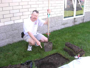
You don't need any special kind of wire for radials, but I recommend a coated (insulated) wire that is not springy and is strong enough to flex multiple times without breaking. Clean off enough insulation to make a good connection to the central grounding point, then run each wire out across the yard, approximating its final position. The wire only need be just beneath the sod. There is no reason to bury it deeper, so you can cut the sod with something like an edge trimmer and just poke the wire down into the cut. Before doing ANY digging, check to be sure you are not going to run into any buried utilities or your lawn's irrigation system.
Stomp the grass back down and you are good to go. Repeat for each radial. If you can go out 33 feet in one direction and only 15 in another, that's okay. Just make sure that the final installation is solidly connected to the ground rod and coax braid and all of the wires are out of the way of the lawn mower. The insulated wire will last longer in the ground than non-insulated wire. Once you get a taste of a hands-and-knees radial installation, you will not be eager to repeat it to replace rotted out wire any more than you have to. And if you tried to install springy radial wire, well, you know what that is like. Push one part in, another part pops out.
When the radial field is in place, a test will include an SWR check. If you find that the SWR has gone UP, you should not be alarmed. The feedpoint impedance of a vertical is generally well below 50 ohms, so it is quite possible that all that loss resistance in the soil had been adding to the impedance to make the end result a better match before than it is now! You should not worry unless the SWR is really high, though. In fact, the somewhat higher SWR is an indication that you have cut ground resistance and improved conductivity, thus increasing your antenna's efficiency. Turn on the rig, try calling some stations, and you will find out that more of your signal is going out onto the air!
Email me at handiham@couragecenter.org with your questions & comments. Patrick Tice, WA0TDA
Handiham Manager